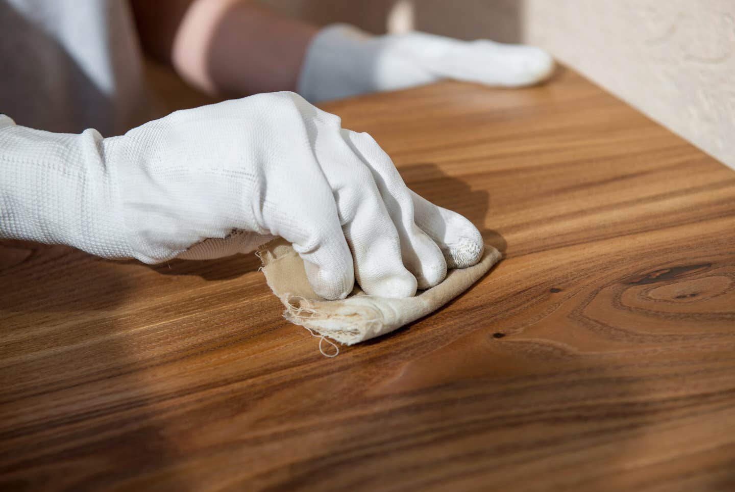
Sanded finish should always be consistent
Table A allows you to compare abrasive belt mineral sizes based on several different grading systems. Please note that the P-designated belts (European grades) are a different mineral size than…
Table A allows you to compare abrasive belt mineral sizes based on several different grading systems. Please note that the P-designated belts (European grades) are a different mineral size than the X-designated belts (U.S. grades] except for 180 grit.
Generally speaking, P-graded minerals are larger or coarser than X-graded minerals. (A P100 grade belt has slightly larger minerals than a 100X belt and can therefore theoretically give a minutely coarser overall finish.) However, P-graded belts will have less size variation in the actual grit particles within a belt than X-graded belts and therefore give a more uniform consistent sanded finish.
In the abrasive belt making process, minerals are first crushed and then sorted by size. Using the American National Standards Institute grading system, a given grit belt has a percentage of both larger and smaller minerals than the target grade size. Smaller size minerals do not cause any problems, but any larger size minerals can result in some wild scratches.
Using the Federation of European Producers of Abrasive Products grading system, a much smaller percentage of larger and smaller minerals are prevalent and also the size range of these maverick minerals is much reduced.
Therefore, to obtain the most uniform consistent sanded finish, P-graded abrasive belts should be used.
Running test boards
Using the information provided in previous articles, you are now well on the way to establishing a sanding process to maximize quality and belt life and eliminating the normal problems. The next step requires an honest assessment of where you currently are regarding your sander’s operating parameters.
This method will require the use of a vernier caliper to assist in the calibration of the machine. Obtain an MDF panel and rip three strips approximately 2” wide. The length of the board should be long enough to fit under all heads with at least some material sticking out from each end of the machine.
Set the machine thickness to assure that material will be removed from all heads. With all heads running and the conveyor belt stopped, position boards across the width — one on each edge and one in the center. Start the conveyor and send all three boards evenly into the machine. Once the trailing end of the boards have reached the beginning of the machine, press the emergency stop. Next, lower the bed to remove the boards to be removed from the machine. The boards should look like the sample in Diagram 1.
Test boards will show how much material is actually being removed by each head and provide the operator with an example of each scratch type and which head assembly provided the scratch.
Depth of cut
A simple depth-of-cut measuring device can be used to directly measure the depth of cut being taken by each sanding head on the test board.
1. With sanding heads shut off, open the thickness setting on the sander to approximately 5” (lower the feed bed).
2. Slide the setup device on the conveyor belt on one side of the machine under the first sanding head (with an abrasive belt on the head).
3. Close the aperture until the dial indicator starts to register (can be closed to a specific reading on the dial, but not necessary).
4. Slide the device under the next sanding head with its belt on. Note the differential in thickness readings.
Repeat Step 4 for each additional sanding head.
This article originally appeared in the August 2012 issue.
A.J. Hamler is the former editor of Woodshop News and Woodcraft Magazine. He's currently a freelance woodworking writer/editor, which is another way of stating self-employed. When he's not writing or in the shop, he enjoys science fiction, gourmet cooking and Civil War reenacting, but not at the same time.

