Adjustment of wide belt sander can be tricky
In previous issues, we have addressed the following questions: • What is the depth of scratch resulting from each grit abrasive belt being used? • What is the maximum amount…
In previous issues, we have addressed the following questions:
• What is the depth of scratch resulting from each grit abrasive belt being used?
• What is the maximum amount of material that can be removed at the feed speed required?
• Based on that information and the machine that I have, what grit sequence should be used?
• What am I currently removing with each abrasive head?
• How do I compare with the target?
Now we are ready for the most difficult and time-consuming part of our process. How can I adjust my machine to get from where I am to where I should be?
Almost every wide belt sander built anywhere in the world uses eccentric arrangements to adjust individual contact drums and polishing platens. The resulting vertical movement is therefore non-linear, which means any adjustment device on the machine does not move the drum or platen vertically the same amount for each graduation on the machine’s indicating scale.
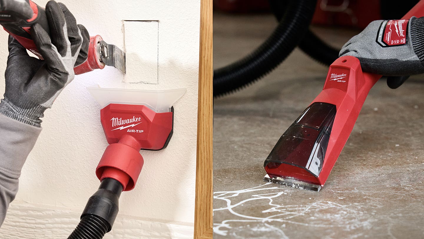
A few newer machines have incorporated a separate dial indicator that will accurately show the exact amount of vertical movement at least on one side of the drum or platen. However, 95 percent of all sanders in the field do not have these separate dial indicators. The best and oftentimes the only solution to this problem is to either make or purchase a sander setup/diagnostic device and follow these instructions. (shown in photo, opposite page)
To set sanding head differential:
1. Shut off all sanding heads and open the thickness setting on the sander to approximately 5” (lower the feed bed).
2. Slide the setup device on the conveyor belt on one side of the machine under the first sanding head loaded with an abrasive belt.
3. Close the aperture until the dial indicator starts to register (can be closed to a specific reading on the dial, but not necessary).
4. Slide the device under the next sanding head with its belt on. This head can now be adjusted (using the individual head adjustment) until the correct differential setting is obtained.
Repeat Step 4 for each additional sanding head.
To check side-to-side position of sanding heads:
1. Open the thickness setting on the sander to approximately 5” (lower the feed bed).
2. Slide the setup device on the conveyor belt on one side of the machine under the first sanding head without an abrasive belt on the head.
3. Close the aperture until the dial indicator starts to register (can be closed to a specific reading on the dial, but not necessary).
4. Slide the device to the other side of the machine while keeping it positioned under the same sanding head. Make any required side-to-side adjustments on the machine so that the dial indicator reads the same on both ends.
Repeat Step 4 for each additional sanding head.
To set relative height and side-to-side settings of pinch rolls and shoes relative to sanding heads:
1. Open the thickness setting on the sander to approximately 5” (lower the feed bed).
2. Slide the setup device on the conveyor belt on one side of the machine under the first sanding head with an abrasive belt on the head.
3. Close the aperture until the dial indicator starts to register (can be closed to a specific reading on the dial, but not necessary).
4. Slide the device under each pinch roll and each hold-down shoe making the necessary adjustments until the correct differential settings and side-to-side settings are obtained.
To check sanding heads, pinch rolls and shoes for wear across the face:
1. Open the thickness setting on the sander to approximately 5” (lower the feed bed).
2. Slide the setup device on the conveyor belt on one side of the machine under the sanding head, pinch roll — or shoe — until the dial indicator starts to register. Then move it laterally across the width of the machine while making note of any dial indicator needle movements. Contact drums or platens should be straight within .002”. Pinch rolls should be straight within 1/32”. Hold-down shoes should be flat within .002”.
Repeat Step 2 for each additional pinch roll or shoe.
To check runout of contact drums:
1. Open the thickness setting on the sander to approximately 5” (lower the feed bed).
2. Slide the setup device on the conveyor belt in the center of the machine under the first sanding head without an abrasive belt on the head.
3. Close the aperture until the dial indicator starts to register (can be closed to a specific reading on the dial, but not necessary).
4. Release the brake on the sanding head if necessary.
5. Slowly turn the contact drum by hand while observing the needle on the dial indicator. Runout should not exceed a total of .001”. Depending on the hardness of the drum, runout greater than this can cause chatter marks.
For help with sanding problems, contact: Howard Grivna, Sanding Systems Consulting Inc. Tel: 218-678-2929. www.sandingsystemsinc.com
This article originally appeared in the September 2012 issue.
A.J. Hamler is the former editor of Woodshop News and Woodcraft Magazine. He's currently a freelance woodworking writer/editor, which is another way of stating self-employed. When he's not writing or in the shop, he enjoys science fiction, gourmet cooking and Civil War reenacting, but not at the same time.